工業設備技術領導者 (儲冰槽、冷卻水塔、發電機激磁系統)
Global Leader in Ice Thermal Storage
![]()
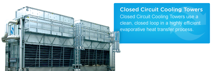
Closed circuit cooling towers provide evaporative cooling for many types of systems, and the specific application will largely determine which BAC Closed Circuit Cooling Tower is best suited for a project. Comparison Table Specialized assistance is available through your local BAC Representative.
Principle of Operation
Closed circuit cooling towers operate in a manner similar to open cooling towers, except that the heat load to be rejected is transferred from the process fluid (the fluid being cooled) to the ambient air through a heat exchange coil. The coil serves to isolate the process fluid from the outside air, keeping it clean and contaminate free in a closed loop. This creates two separate fluid circuits: (1) an external circuit, in which spray water circulates over the coil and mixes with the outside air, and (2) an internal circuit, in which the process fluid circulates inside the coil. During operation, heat is transferred from the internal circuit, through the coil to the spray water, and then to the atmosphere as a portion of the water evaporates.
Configuration
BAC manufactures two types of closed circuit cooling towers: combined flow and counterflow.
Combined Flow
Combined flow is the use of both a heat exchange coil and fill for heat transfer in a closed circuit cooling tower. The addition of fill to the traditional closed circuit cooling tower design reduces evaporation in the coil section, reducing the potential for scaling and fouling. BAC’s combined flow closed circuit cooling towers utilize parallel flow of air and spray water over the coil, and crossflow air/water flow through the fill.
In parallel flow, air and water flow over the coil in the same direction. The process fluid travels from the bottom to the top of the coil, increasing efficiency by bringing the coldest spray water and air in contact with the process fluid at its coldest temperature.
In the fill of BAC’s combined flow closed circuit cooling towers, air and water interact in a crossflow configuration: water flows vertically down the fill as air flows horizontally across it.

Combined Flow: Parallel Flow of Air and Water Over the coil

Combined Flow: Crossflow Configuration Over the Fill
Counterflow
In a counterflow closed circuit cooling tower design, the flow of the air is in the opposite direction of the spray water. In BAC’s counterflow closed circuit cooling towers, air travels vertically up through the unit while the spray water travels vertically down over the coil. The process fluid flows from top to bottom through the coil and is in thermal counterflow to the air.

Counterflow Configuration
Fan System
The flow of air through most factory assembled closed circuit cooling towers is provided by one or more mechanically driven fans. The fan(s) may be axial or centrifugal, each type having its own distinct advantages.
Axial fan units require approximately half the fan motor horsepower of comparably sized centrifugal fan units, offering significant lifecycle cost savings.
Centrifugal fan units are capable of overcoming reasonable amounts of external static pressure (≤ 0.5”) 12.7mm of H2O, making them suitable for both indoor and outdoor installations. Centrifugal fans are also inherently quieter than axial fans, although the difference is minimal and can often be overcome through the application of optional low sound fans and/or sound attenuation on axial fan units.

Centrifugal Fan

Axial Fan
Induced Draft
Fans can be applied in an induced draft or a forced draft configuration. The rotating air handling components of induced draft equipment are mounted in the top deck of the unit, minimizing the impact of fan noise on near-by neighbors and providing maximum protection from fan icing if units operate in sub-freezing conditions. The use of corrosion resistant materials ensures long life and minimizes maintenance requirements for the air handling components.
Forced Draft
Rotating air handling components are located on the air intake face at the base of forced draft towers, facilitating easy access for routine maintenance and service. Additionally, locating these components in the dry entering air stream extends component life by isolating them from the saturated discharge air.
Capacity Range
Product capacities are called out in terms of a flow rate at 95ºF/85ºF/78ºF. This refers to the flow rate of water that the unit can cool from a 95ºF (35.0ºC) entering water temperature to an 85ºF (29.4ºC) leaving water temperature at a 78ºF (25.6ºC) entering wet-bulb temperature. BAC offers selection software to evaluate the performance of a closed circuit cooling tower at any conditions.
All capacities shown are for a single cell; multiple cell units can be applied to achieve larger capacities.
Maximum Entering Water Temperature
All BAC Closed Circuit Cooling Towers are capable of withstanding entering fluid temperatures as high as 180ºF (82.2ºC), and the HXV is capable of withstanding even higher temperatures due to the added dry coil technology.
Advantages of Closed Circuit Cooling Towers

Figure 1: Chiller Loop with Cooling Tower
Open cooling towers expose process cooling water to the atmosphere, typically as part of a chiller system loop. Open towers use an efficient, simple, and economical design. All components in an open system must be compatible with the oxygen introduced via the cooling tower.

Figure 2: Chiller Loop With Closed Circuit Cooling Tower
Closed circuit cooling towers completely isolate the process cooling fluid from the atmosphere. This is accomplished by combining the heat rejection equipment with a heat exchanger in a closed circuit tower. A closed loop system protects the quality of the process fluid, reduces system maintenance, and provides operational flexibility at a slightly higher initial cost.
When deciding which system is best for an application, several factors should be considered.
Performance
If an application must produce full capacity throughout the year, maintaining a clean, reliable system loop is critical. Isolating the process fluid in a closed loop system prevents airborne contaminants from entering and fouling the system. Sustaining optimum performance in an open loop system will require regular maintenance to assure similar efficiency. High efficiency chillers and heat exchangers rely on clean process water to function properly and are significantly impacted by even small amounts of fouling.
Expense
The initial equipment cost of an open loop system will be less than a comparably sized closed loop system, since the open system does not include the intermediate heat exchanger component. However, the higher first cost of a closed loop system will be paid back during years of operation through the following savings:
- Cleaner process fluid results in a cleaner internal surface area, and higher efficiency components in the system (e.g. chiller)
- Reduced system maintenance costs
- Reduced water treatment costs for evaporative equipment
- Operating in ’free cooling’ mode during the winter to save energy consumption
Maintenance
Since the process fluid of a closed loop system is completely isolated from the environment, routine maintenance is only required on the heat rejection equipment itself. The need to shut down the system periodically to clean the heat exchanger is dramatically reduced, if not entirely eliminated. Providing clean process fluid to the system will extend the life of other components in the system (condenser bundles, compressors, etc.).
Water Treatment
Maintaining proper process fluid quality in a system may involve several steps, such as chemical treatment, filtration equipment and the addition of clean make-up water. A closed circuit cooling tower can provide the following advantages over an open cooling tower:
- Lower volume of recirculating water to treat
- Process loop requires minimal treatment
- During periods of dry operation, the need for make-up water is eliminated
Operational Flexibility
Closed circuit towers allow for the following modes of operation not possible with open towers:
- Free cooling operation without the need for an intermediate heat exchanger: Chiller turned off
- Dry operation: Conserve water and treatment chemicals, prevent icing and plume
- Variable pumping: Closed condenser water loop allows for variable speed pumping to conserve energy
Closed Circuit Tower vs. Open Tower / Heat Exchanger

Figure 3: Chiller Loop With Cooling Tower/Heat Exchanger Combination
Sometimes, an open cooling tower is paired with a heat exchanger to capture some of the benefits of closed loop cooling. Choosing closed circuit cooling towers over this open tower/heat exchanger combination may still be a better choice for the following reasons:
- Total cost: Addition of a heat exchanger (pump, piping, etc.) to the open tower loop brings the initial cost much closer to that of the closed circuit tower system
- Single piece of equipment: Compact design of the closed circuit tower conserves space in a self-contained package, compared to multiple locations for the tower/heat exchanger arrangement
- Maintenance: Narrow spacing in the heat exchanger (e.g. plate and frame) may trap solids introduced by the open tower, requiring frequent, time consuming cleaning to assure optimum performance
- Dry operation: Open tower/heat exchanger system cannot be run dry in the winter
These guidelines provide some general information to help decide whether a closed circuit cooling tower is better suited for a particular application than an open tower, with or without a heat exchanger. For additional assistance with a project, please contact your local BAC Representative.
關注我們